
by James D. Banister, BS, MBA, AMPM, LSS BB, Bobst North America Inc.
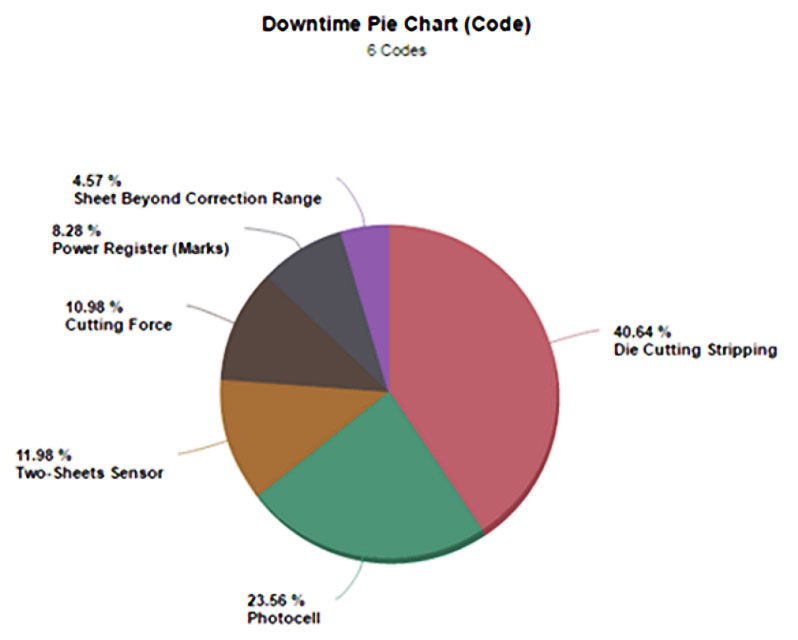
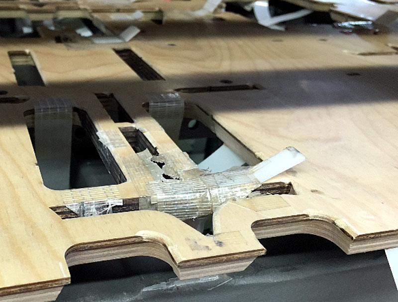
The problem operators face today is the process of effectively removing the internal or external (trim) waste material from the diecut sheet at high speeds. Data validates that the stripping section is a critical reason why machines stop (see Diagram 1). Sheets break apart – leaving cartons, trim waste or scrap pieces lying on or sliding across the central stripping board, tripping off the machine photocells that are located between the stripping and blanking sections (see Diagram 2).
The other problem is that management focuses, in my opinion, more on the cost of a finished tool, or the materials (pins, claws, etc.) than the actual money hemorrhaging from the bottom line when the machines are down, waiting while personnel are creating, adjusting, fabricating or setting lower pins to get a stripping set of tools to perform. The truth is that the operator has little or no control over how well the stripping tool is going to perform. Why?
Critical requirements outside the operator’s control:
- Machine condition: This is the most important and includes gripper bars, chains, Bernoulli, etc. Proper annual maintenance and the amount of chain stretch are critical to successful stripping. The smaller the waste, the more important it is – regardless of the stripping technology.
- Structural design: Waste areas in designs and layouts smaller than 4.5 to 5 mm (0.177″ to 0.197″) in width.
- Layouts: Not turning flute/grain direction of layouts based on what is required to strip. Thin and small pieces should be perpendicular to the gripper edge.
- Natural nicks (knife joints) and nicks not in correct locations.
- CAD: Not properly placing carrier rule to help guide the blanks over large stripped areas and not placing numbers in scrap areas to print.
- The lower board skiving and foam placement on the upper tool.
- The lack of properly supporting the central stripping board with steel rails under the tool – for the larger format machines, especially.
- Stripping or removing too much waste, thus creating an unstable sheet at high speeds.
- Inferior quality pins utilized in the upper tool that are not sharp or hardened.
- Non-perpendicular or skewed upper tool components manually pounded into the upper, causing the tool pins and blades to be non-perpendicular in various directions, thus creating problems in tight areas and compounded with gripper bar and chain variation.
- The material: Curl, moisture or printing not centering the sheet or not planning enough side or back trims to effectively remove the trim in the stripping process.
- Not utilizing quick locking technology to avoid frame-to-frame variation.
Critical stripping functions inside the operator’s control:
- Validate the tool alignment during the makeready process.
- Don’t tap upper tool components to avoid marks on the cartons. This usually creates more issues and weakens the tool.
- Don’t add nicks to scrap areas in incorrect areas: The die should match the dynamic stripping requirements to balance and hold the scrap. Only make existing nicks slightly larger.
- Properly handle the tooling during every step between the assembly, makeready and storage of the tools.
The history of stripping tools
As cutter technology and speeds advanced, so have the tooling fabrication and performance requirements. Stripping tooling is no different. The following four core historical stripping technologies represent the movement post-clamshell diecutting to the fastest diecutter running at 12,000 sheets per hour. Each of these core stripping systems has its pros and cons, but when weighed on the balance of cost and productivity, they are not equal.

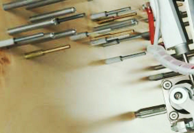
Universal (see Diagram 3)
Pros
- Reusable upper pins
- Tools can be manually made or remade on site
Cons
- Labor intensive off press and on press
- Weight of the pin rack requires two people to lift, even for 3B format
- Machine downtime for adjustments
- Requires lower pins set-up
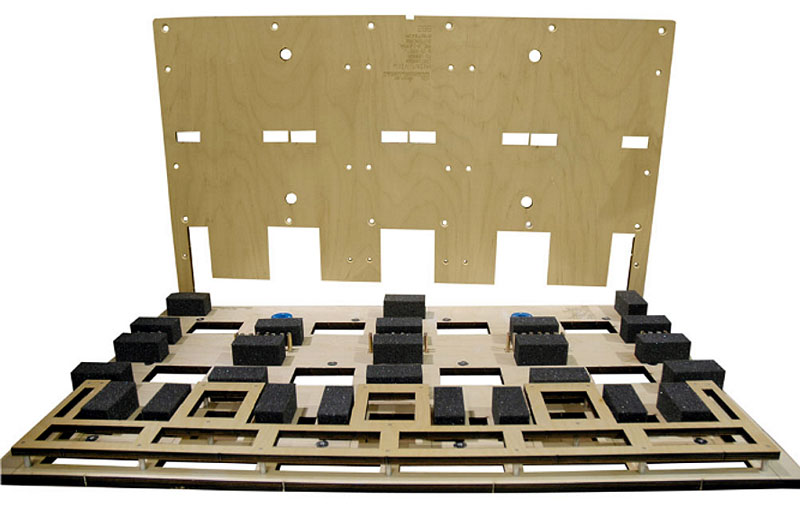
Conventional (see Diagram 4)
Pros
- Generally sold at a lower price vs. dynamic
- Tools can be fabricated on-site
- Generic CAD programming offsets
Cons
- Labor off press and on press
- Machine downtime for adjustments
- Requires lower pins labor each run
- Actual cost of materials is not less than dynamic

Dynamic – made conventionally using hammer for assembly (see Diagram 5)
Pros
- Generally effective and reduces most lower pins
- Tools can be manually fabricated on-site
- Customized CAD solutions can be manually created for upper/central components/interferences
- Can adapt several components in the upper tool, such as pins, claws and wood blocks
Cons
- Cost is higher than dynamic made digitally
- Requires the use of a router or laser to precut the slots and holes into upper stripping board
- Manual insertion of components into upper board can bend components, causing them to be non-perpendicular across the tool, resulting in considerable problems on small scrap pieces
- A poor laser or router preparation can cause loose pins, blades and claws, causing production problems or failure
Dynamic hybrid – totally digital with automated assembly (see Diagram 6)
Pros
- The lowest cost solution since the first universal stripping systems were introduced
- Generally effective and reduces most lower pins and machine adjustments
- Only system capable of creating a 3D upper tool
- At a previous drupa, a digital hybrid machine was released that can place crown pins and claws into the upper tool without the need to precut the upper stripping board
- Another option to the digital stripping portfolio is a pin-setting digital machine to automatically set all pins, but if claws are needed, they can be manually inserted into a precut slot
- Customized CAD solution exists to create tools quickly
- All of the components placed into the upper board are perpendicular to eliminate most sheet breakups at high speeds and provide the safest elimination of damage to the brand owner’s product in tight areas
Con
- To eliminate the assembly labor and quality variation, the immediate con is the investment for the acquisition of this new hybrid (digital) automated pin and claw manufacturing machine.
The core requirements of dynamic stripping
To effectively remove waste at high speeds without the use of lower pins requires perfect CAD preparation and controlled nicking of the die. The following functions must be addressed when designing a functional dynamic stripping tool.
Nicking
Nick placement in the dieboard is completely dependent on the relationship between the upper component and the lower interference. This is an important requirement for stripping success, but only one CAD software today has automated the nick placement in the dieboard to control accuracy during the stripping tool programming process. When the user is placing the lower interferences and the upper tool components, a nick also can be placed simultaneously in the dieboard file, making the process more secure and providing the operator the best opportunity for success.

Unlike conventional stripping, most waste generally needs to be nicked in at least four areas to guarantee the elimination of lower pins (see Diagram 7). This is contradictory to what operators and diemakers think and have been taught, as most have always been taught to nick only the lead edge of scrap areas.
Balance
The waste must be balanced on both the upper tool components and in the resistance during the stripping expulsion process. Successful stripping without lower pins is achieved when the waste material is balanced on as many planes as possible. Tight slots force the diemaker to use a straight upper component (claw, steel rule, etc.), and this only controls the scrap on a single plane – causing the most problematic issues in stripping.
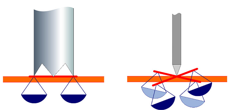
Diagram 8 demonstrates the balance of the scrap on a crown pin vs. the unstable scenario presented with a single claw or steel blade. As for the balance of the resistance, if a waste area is large enough to support four restriction plus pin combinations, the scrap piece cannot twist, and the resistance from the combination of the nicks and restrictions is balanced so the force of the upper tool can explode the waste below the restrictions embedded in the lower tool board, never to come back out the top of the board. For very small scrap slots, it is only recommended to nick very small and offset on one side of the slot from the other side. Reverse nicks on steel counters also can be helpful.
Quality of components
In our analysis, we have looked at many crown pins and other male stripping components sold worldwide and reviewed the performance and quality. We found that only one pin is truly manufactured sharp and hardened. Reviewing customers’ tooling, these quality hard pins have outlasted the life expectancy of the tooling. Substitute technology may save a few cents per pin, but they are soft steel or brass, and they do not effectively “prick and control” the scrap like the original hard sharp pins. Look how the scrap pieces are stabbed by the original pin – this is a must to have true success in dynamic stripping. By spreading those few pennies of savings over the average amount of pins utilized a stripping tool set, this difference is less than a few percent, and when the manufacturer has to add or adjust lower pins, the cost savings on soft pins can be eroded with only three to five minutes of machine downtime or pre-makeready time spent setting lower pins.
3D

Another important factor is to understand the stress of the diecut sheet during the stripping process. When the sheet is in contact with the upper tool components, it is stressed in many directions. Extensive foam must be placed to control the sheet from breaking apart at high speeds. Digital 3D capabilities allow the stripping tool to be programmed in zones where the components are placed at different heights, so each zone contacts the sheet at different times – thus reducing the force and stress on the sheet
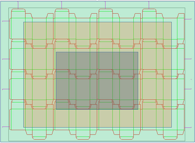
(see Diagram 9). The trim areas need to be removed first (level 1 in light blue) and the center of the layout should be removed last (level 3 in dark gray) (see Diagram 10). Do the dynamic stripping technology and the CAD system your organization utilizes support the 3D capabilities?
Restrictions
Restrictions have many shapes and forms. The most common and least expensive is to use the lower board wood specially cut to extend past the diecut knife and under the scrap waste on the lower board. Other stripping systems require objects to be manually inserted into the lower tool board to create the interference. These generally can work over a period of time before these inserted components wear or break and also add cost to the tools.
Offsets
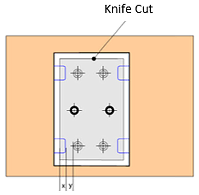
The last core technological requirement of effective dynamic stripping without lower pins is the offsets programmed between the male component and the lower restriction and die knife. Another important consideration is the material being processed. The offset dimensions (x,y in Diagram 11) should change when processing certain types of materials such as flute, paper, etc. It’s even better if the CAD system can dynamically adjust these offsets based on the material selected in the job project. Without going into much detail, as each system basically uses different offsets, a good rule of thumb is 2 mm (0.079″) for both the x and y dimensions. This means the lower board restriction is 2 mm (0.079″) under the scrap and the upper interference is 2 mm (0.079″) away from the edge of the restriction. The lower board opening is approximately 1.5 mm or 3 mm (0.059″ or 0.118″) overall larger than the cut area.
The final analysis
Zone of influence
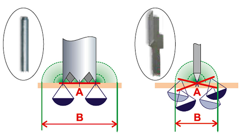
The evaluation process is based on performance and cost. Diagram 12 demonstrates the influence of a crown pin vs. a single claw. In it, sharp, pointed and hardened crown pins balance “A” (the scrap on all planes) as well as control “B” (more area). I like to call this the “zone of influence.”
“1 vs. 3” dynamic
Upon evaluation, many scrap pieces generally would need three claws or blades rotated at different angles to do the function of what one crown pin can provide to control the scrap area from the top down.
Cost
Although Bobst does not sell or manufacture stripping tooling, we have purchased many tools from many organizations worldwide for new machine performance testing. Productivity and performance always will outweigh the cost of a tool, and should, if the benefits of machine productivity (overall equipment effectiveness or OEE) are greater than the cost of the tooling or the cost of the labor to create the tool and the pin racks set up, even if the tool was a one-time run.
Conclusion
On average, with the combination of related CAD automation and proper training, the new hybrid dynamic digital stripping system (pin and claw automatically inserted) or the existing automated pin setting system utilizing certified components, are the best performing technologies as well as the lowest cost solutions on the market.
James D. Banister is the continuous improvement technical manager at Bobst North America Inc. He may be reached by email at james.banister@bobst.com. For more information, visit www.bobst.com.
Reprinted with permission from The Cutting Edge.