
By Joe McDowell, vice president, Channel Creasing Matrix/CCM Die Supply
It is important in most everything to understand both the how and why to solve issues and teach people the best solutions. As it relates to creating a quality crease during diecutting, a better understanding of how and why a crease forms in various substrates can lead to better outcomes. Although the results will vary based on specific conditions and situations, most people can achieve the same result if they simply follow the proven formulas and communicate.
With the many changes in substrates on the market today, there still are three basic ways to crease materials during the diecutting process – matrix, phenolic counter or steel counter plate. Which of these is the best way to crease the product? The answer could be all of them, depending on the substrate qualities and characteristics. To be clear, this article only is addressing flat diecutting. Rotary diecutting is something completely different. To simplify, it may be helpful to categorize the substrates into three categories.
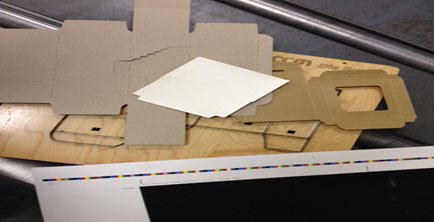
- Fibrous material – This would encompass any material made up of paper fibers that are compressed together to form a sheeted material. These generally are known by some of the following names: SBS, CCNB, chip, Kraft back, recycled board, etc. These are the materials seen every day in cartons, folders, mailings, etc.
- Fluted materials – Generally known as corrugated or cardboard. This material usually is a Kraft material either found in brown box form or, more and more, in shelf-ready display or POP display. Many times, these fluted materials can be found either printed directly on or laminated with a label or fiber board material. This can cause many problems depending on the material laminated.
- Plastic cartons – People are looking at this style of carton for a variety of reasons, one of them being the visualization of the contents, readily seen with the simplicity of the print. Another positive about this type of product is the virtual lack of moisture degradation that occurs if it gets wet. Creasing of this type of material normally is not done with a counter material. It can be, but normally it is done with a form of slitting or by perforating the plastic.
There are many determining factors when trying to crease fiber board. The following are a few considerations:
- The design of the finished product. Finding the proximity of the creases to each other and the cutting rule can lead to variations in the die manufacture and counter used.
- The substrate to be used. Various substrates have different characteristics, and they all will have unique attributes that need to be handled accordingly.
- The type of press to be used. Is it a platen style or a cylinder press? Many people ask if it really makes a difference. The answer is: Absolutely. There are many ways to get around the differences, but they all entail a little work, and, if not done correctly, can cause more problems on press that may not seem to be, but can be, related to creasing.
- The length of the run of the product. Some counter materials are made for short runs of 15,000 or less, while others can run hundreds of thousands of impressions.
If these items are not discussed in more than a passing conversation, it is guaranteed there will be a problem during the diecutting process. Sometimes that problem is taken as status quo. For example, a long makeready may seem like standard practice; however, it doesn’t have to be.
In many cases, the problem lies in the communication, or lack thereof, between the diemaker and the diecutter. If a diecutter would tell the diemaker about the problems that are occurring, the diemaker may make some suggestions or changes. On the other side of that coin, the diemaker needs to ask some of these questions to make sure the best tooling possible is being made.
Understanding folds
To understand why fiberous material folds the way it does, it is important to look at the makeup of the material.

With a common SBS board, the fibers are bonded together and run in the same direction. Thus, the material can be creased with grain (creasing in the same direction as the grain) or cross grain (where the crease runs perpendicular to the grain direction). The proper way to get a good crease is to break or delaminate these fibers while stretching the upper and lower liners of the material. How fibrous paper reacts under pressure and what causes the material to delaminate has been studied – not only the vertical pressure of the crease rule but the lateral pressure as well. This lateral pressure comes from the material being forced into a narrow channel. In the old days, the formula used to be 2 x the paper thickness + the crease rule width. This formula would put a line in a piece of paper, allowing it to fold. The problem came as the quality of print increased, different types of printing became available and the drying of the materials evolved. Many of the drying techniques have changed for inks today, and the quality of the material has changed with much of it being recycled. The newer methods of drying have added challenges in the diecutting/creasing processes.
Originally, the creasing rule was 2 x the paper thickness. However, using this formula and trying to fold or bend the paper over without changing the dynamics of the paper (displacing materials) will stretch the face or front liner over a greater surface area, which is created by the mass of material meeting at the crease area. When this happens, there will be cracking all through the crease. The formula used today is 1.75 x material thickness + crease rule width. This formula is based on the principle that proper creasing is created by delaminating the fibers.
This is achieved when the channel that the paper is forced into is narrower than the original formula. This causes the material to pinch at the top of the channel, stretching the upper and lower liners slightly and breaking the bond between the fibers. Now when the item is folded, the lower liner and the fibers that were delaminated move out of the way, and the top liner stretches around a smaller surface area.
As the fibers move out of the way, the face or top liner can wrap around the material without cracking. This is how a crease in fiber material should work, and most times it does. However, there are times when the coating was dried at a greater temperature so it would dry faster, and this causes a dry stock or dry print. This, in turn, may look as if the board is cracking when in fact it is the ink.
Grain direction
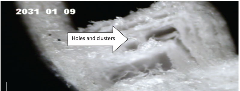
Which way is best to run the crease? Across grain will give a more stable crease than with grain. The reason for this can be found when looking at the way in which the delamination occurs. The material will delaminate in long lines when creasing across grain. However, when creasing in grain direction, a different type of delamination occurs. Imagine the fibers as a bunch of straws in a glass. Now put something in that glass, and the straws will separate but remain in clusters. This is what happens when creasing in grain direction. The fibers have a tendency to cluster.
The delamination is a series of holes or pockets. If these pockets or clusters move too close in the same direction, there may be some cracking, even if the channel width is the same in both directions (with and cross grain). To eliminate this, narrow the channel to the matrix that is the next size down. This will break the clusters down even more. This allows the material to move evenly when folded and not to cluster in the same place.
Another common issue is how to make the crease wider. This can be done by plugging the thickness of the crease rule into the formula. However, this should be done with caution. Although it will provide a quality crease (as far as delaminating), it also will deliver a ropey, wide crease that will not fold squarely. One side or the other of the crease will become dominant, and this dominance will switch from side to side, not remaining constant. A good rule to follow is that the channel width used should be no greater than between three to four times the thickness of the material being diecut. There have been times where 4 ½ is acceptable, but the general rule is three to four times.
Crease rule height
Channel width is very imperative for correct delamination; however, it is not the only factor in obtaining the proper crease. The height of the crease rule also must be considered. The height is calculated by using the following formula: (cutting rule – material being diecut) – (membrane thickness).
The membrane is the material used to hold the matrix together and is present in between the channels. If the material is metal, it is approximately .010″ thick. If it is Mylar or plastic, it usually is .005″ thick. Some believe there is no need to reduce the height of the membrane, but this is not true.
The industry has acceptable tolerances for the materials that go into the diecutting process. Cutting rule and crease rule is +/- .001″. This is potentially a .002″ difference. The cutting plate is +/- .002″, which is potentially another .004″ difference from end to end. In essence, there could be a .003″ difference between the rule and the plate when adding the tolerances together in any given area. Over the length of the plate there can be a difference of .006″. Now the argument will be made to makeready the low areas. This is true but only for the cutting rules.
Back to the formula for the height of the crease rule: Take into consideration the tolerances mentioned in the previous paragraph. If the membrane is not taken out when figuring the crease rule height, it can bottom out on the crease leaving what is called standoff in the cut areas near a crease. The membrane still is in the channel, so the crease rule would push the paper in the thickness of the material, and the membrane, still being intact, would then act as a barrier from the cutting rule making a full cycle. In this case, the diecutter might believe the die is not right, the cutting rule is bad or that it is necessary to stop the press and do makeready. Worse yet, the diecutter adds pressure and forces the cut while the crease cracks. All of these could be avoided if the formula had been followed.
When using a phenolic counter, it is important to know how much material is left in the membrane of the channel. The difference can create challenges with the crease and the cut, as well as cause the problem of standoff.
Many diemakers today have settled at .006″. If the membrane is not taken into consideration, a few different problems can occur. First, the cut doesn’t go all the way through and the product doesn’t strip at all. Second, the product cuts but only in certain areas and ends up with a checking problem (where the bottom ink seems to strip off in pieces). Nicks can become stronger, making blanking or stripping a tougher task and a major makeready delay. And, of course, the crease will be cracked either on the surface or under the ink and can surface on the folder-gluer, if not on delivery.
Common types of cracks
There are several types of cracks normally seen when trying to crease certain papers. Some of the results and causes are discussed in the following:
- Cracking on the sides of the crease (usually noticed on delivery before folding). This usually is caused because the channel is too narrow.
- Cracking on the bottom of the crease (usually noticed on delivery before folding). This is the result of the crease rule being too high.
- Cracking on the folder-gluer, where the crease looks nice on delivery but cracks when folded. Proper delamination has not occurred and too much material is in the way of the top liner. This generally is caused by a crease rule that is too low.
These problems can be avoided by following the formulas and with proper communication between the diemaker and diecutter. There are many other problems that occur because people do not follow formulas nor take into account the collateral damage that can happen when focused on only the problem at hand. When it comes to creasing, some subtle changes can make major impacts on profitability in the diecutting job.
Joe McDowell is vice president of Channel Creasing Matrix/CCM Die Supply. He has been in the converting industry for 30 years and has been studying the effects of creasing on paper and corrugated for the last 25 years. CCM is part of the C&T group of matrix companies. For more information, visit www.ccmdie.com.